
Rotary Joint Application Cases and Selection Examples
See installed rotary-union applications and the information needed to select a model and check the fit.
Real Application Cases
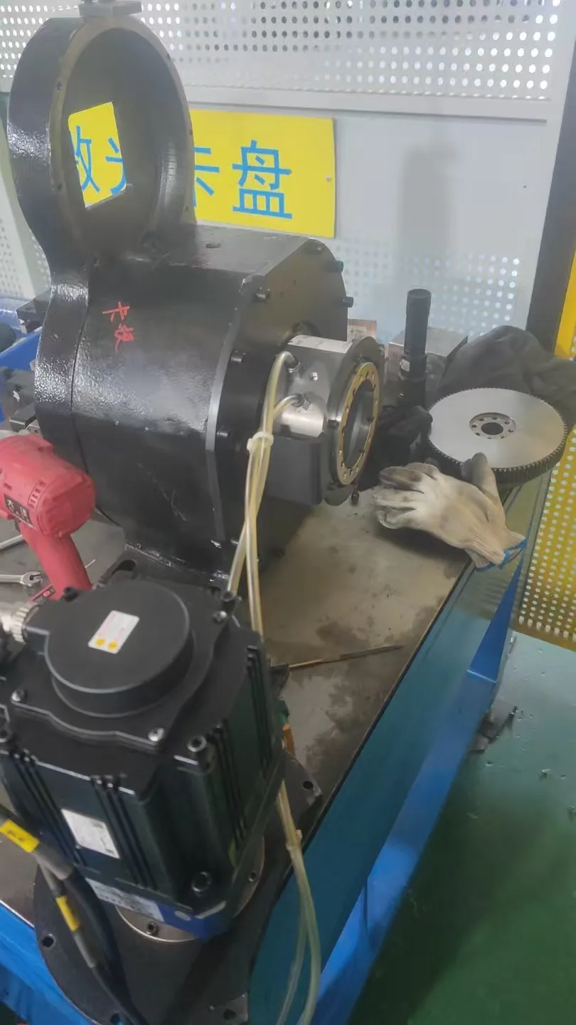
BP-2P-95-0005 in a Pneumatic Chuck Assembly
Pneumatic Chuck Installation
BP-2P-95-0005 supplies compressed air from the stationary side to the rotating chuck in this installation. The detail page shows the mounting position and pneumatic hose routing.
| Item | Application details |
|---|---|
| Product | BP-2P-95-0005 |
| Medium | Compressed air |
| Application | Stationary-to-rotating air supply at a pneumatic chuck |
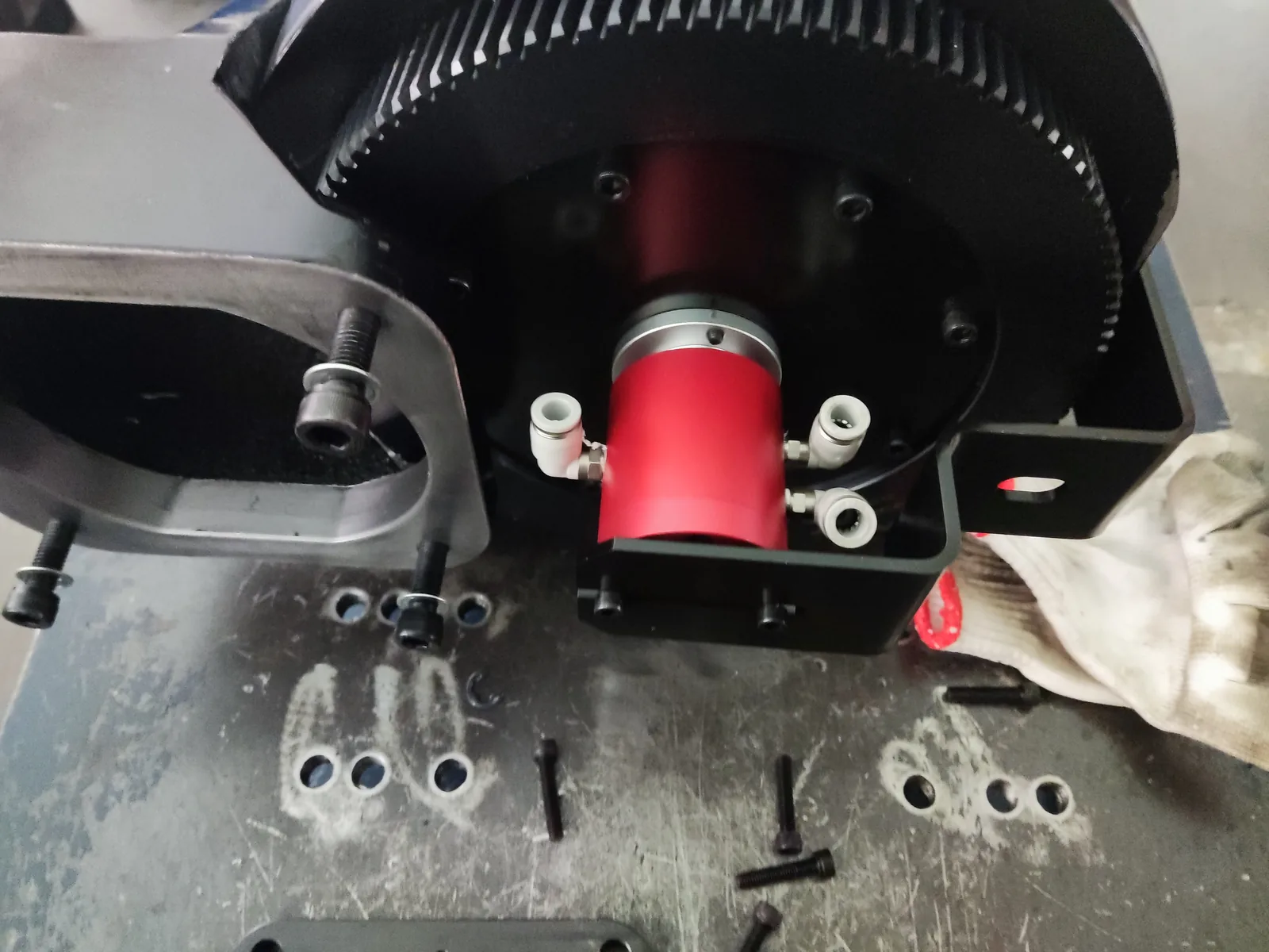
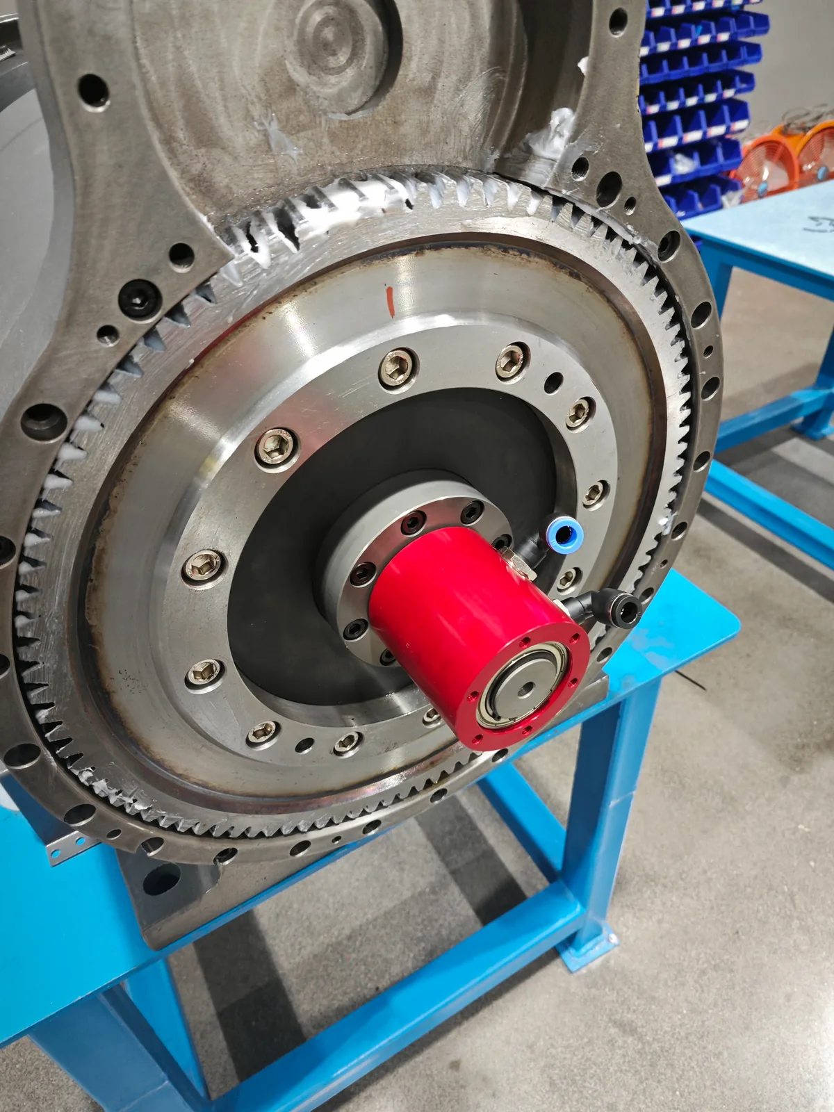
Pneumatic Rotary Union Installation on a Laser Tube Cutting Rear Chuck
Rear-Chuck Installation
Two workshop photographs show pneumatic rotary unions installed near rear-chuck rotating structures, including the chuck structure, mounting area, flange arrangement and pneumatic fittings. The photographs show two installations in this application category.
The rotary union provides a stationary-to-rotating connection for the rear chuck's compressed-air circuits. Passage assignment and operating conditions must be confirmed from the machine documentation.
Begapunk Models Used in This Application
BP-3P-0004 and BP-2P-08-0001 are used for compressed-air circuits in laser tube cutting rear chucks. The photographs show the rear-chuck application; choose the ordered model from the chuck drawing and operating conditions.
| Item | Application details |
|---|---|
| Application | Laser tube cutting machine rear chuck |
| Component | Pneumatic rotary union |
| Application models | BP-3P-0004 and BP-2P-08-0001 for compressed-air circuits |
For a Similar Rear-Chuck Installation
A chuck model, photo, or drawing is enough to start. If known, add:
- Number of independently controlled air functions
- Pressure and maximum or continuous speed
- Mounting interface, available space, and hose direction
For this application, BP-3P-0004 and BP-2P-08-0001 transfer only the rear chuck's compressed-air circuits. Process or assist-gas transfer requires a separate engineering solution.
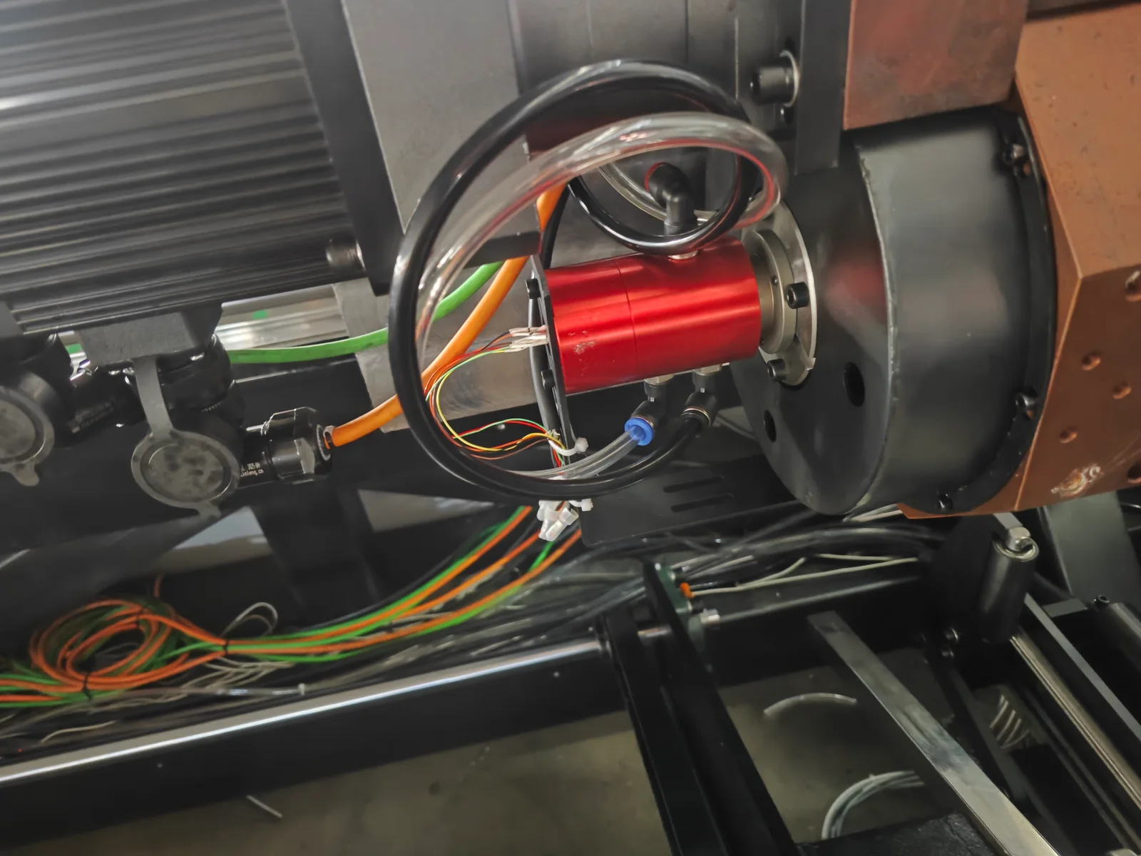
BP-3P-S06-0001 in a Sensor-Monitored Pneumatic Chuck
Customer Configuration
In this customer design, three independent compressed-air circuits are assigned to clamping, unclamping and blow-off. The electrical slip ring transfers external sensor signals that the machine controller may use for workpiece-presence or clamped-position confirmation. Detection remains the responsibility of the external sensors and control system.
| Item | Application details |
|---|---|
| Product | BP-3P-S06-0001 |
| Pneumatic functions | Clamping, unclamping and blow-off in this customer design |
| Electrical role | Transfer path for external sensor signals |
How to Use These Examples
The three entries above show installed applications. The two entries below are selection examples, not customer performance results. Choose the final model from the machine drawing and actual operating conditions.
- Review the mounting arrangement shown.
- Prepare the operating data needed for an RFQ.
- Check dimensions and interfaces against the selected model drawing before ordering.
Engineering Selection Examples
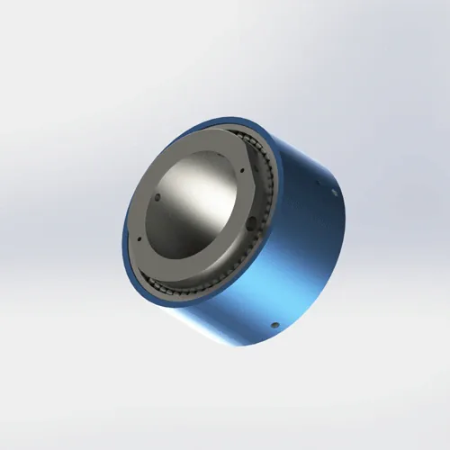
Example 1: Custom Review for Corrosive Outdoor Duty
Engineering Requirement
Salt, humidity, temperature cycling, and difficult maintenance access can change the required housing finish, shaft material, bearing protection, seal compound, and test plan. A standard indoor pneumatic model should not be assumed suitable for offshore service.
| Input required | Why it matters |
|---|---|
| Media and concentration | Determines seal and metal compatibility. |
| Pressure, RPM, and duty cycle | Defines the combined pressure-speed operating point. |
| Temperature range | Affects elastomer selection and dimensional clearances. |
| Corrosion or test standard | Defines coating, material, and validation requirements. |
| Maintenance interval | Influences bearing protection and serviceability. |
Candidate Direction
BP-2P-130-0001 is a heavy-duty catalog reference, not an automatic offshore solution. Any corrosive or safety-critical application requires drawing review, material confirmation, and an agreed validation plan.
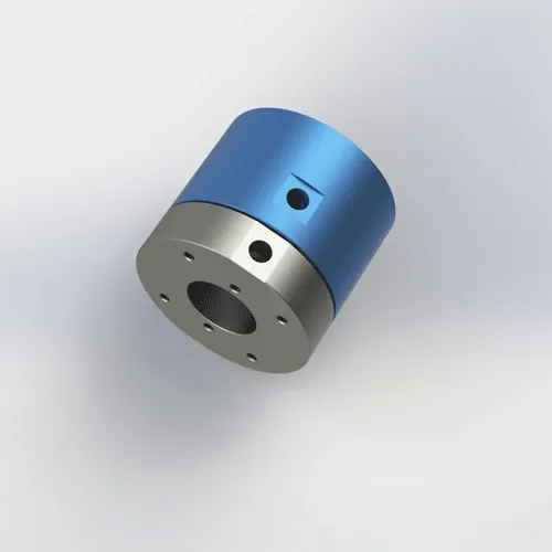
Example 2: CAD Fit Check Before CNC Installation
Engineering Requirement
Even when pressure and RPM are suitable, installation can fail because of bolt-pattern mismatch, insufficient hollow-bore clearance, hose interference, or rigid piping loads. A CAD fit check reduces dimensional risk before production.
| Check | Required confirmation |
|---|---|
| Hollow bore | Clearance around the shaft, drawbar, cable, or tooling. |
| Envelope | Body diameter, total length, and service access. |
| Mounting | Bolt circle, thread specification, depth, and locating feature. |
| Ports and hoses | Fitting size, bend radius, and freedom from external load. |
| Operating point | Media, normal pressure, peak pressure, RPM, and duty cycle. |
Candidate Product
BP-2P-30-0001 is a hollow-bore catalog reference. Download or request the current drawing and confirm all interfaces and operating conditions in the machine assembly before ordering.
Application Cases and Selection Examples FAQ
Where can I review the detailed installation cases?
Are product models confirmed for the laser rear-chuck application?
What can I send to start a model recommendation?
What does the STEP file confirm?
Products Connected to These Cases and Examples
Models Used in Real Applications
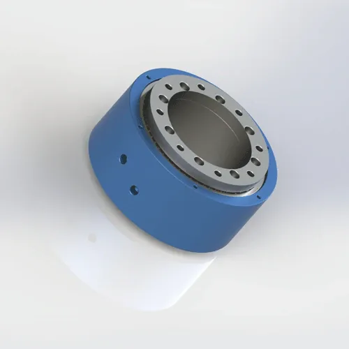
BP-2P-95-0005
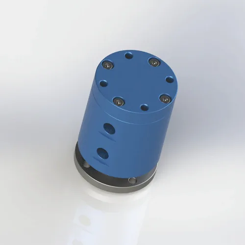
BP-3P-0004
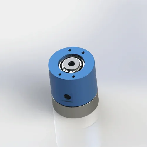
BP-2P-08-0001
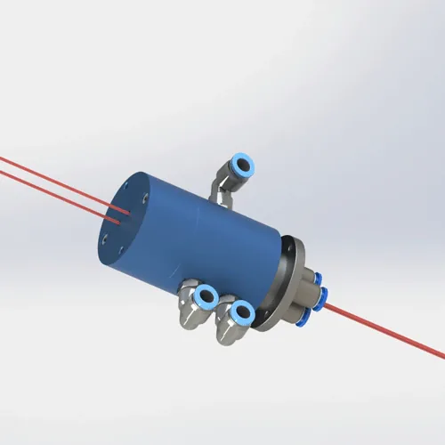
BP-3P-S06-0001
Reference Models in Engineering Selection Examples
BP-2P-130-0001
BP-2P-30-0001
Discuss Your Application
Send the machine type, operating conditions, quantity, and any drawing or product photo you already have. We will reply with a suitable model or custom route, quotation, estimated lead time, and available CAD files.
Get a Quote →