
Pneumatic Rotary Unions for Laser Tube Cutting Rear Chucks
Compare two- and three-passage options for carrying compressed air to a rotating rear chuck.
Carry independent air functions into the rotating chuck
For: Laser tube cutting machine builders and engineers integrating the rear-chuck pneumatic system.
The rotary union connects the stationary air supply to independently controlled functions in the rotating rear chuck. The passage count follows the number of air functions that must remain separate.
BP-3P-0004 and BP-2P-08-0001 are standard starting points for this application. The workshop photographs show the installation type; the exact model in each image has not been identified.
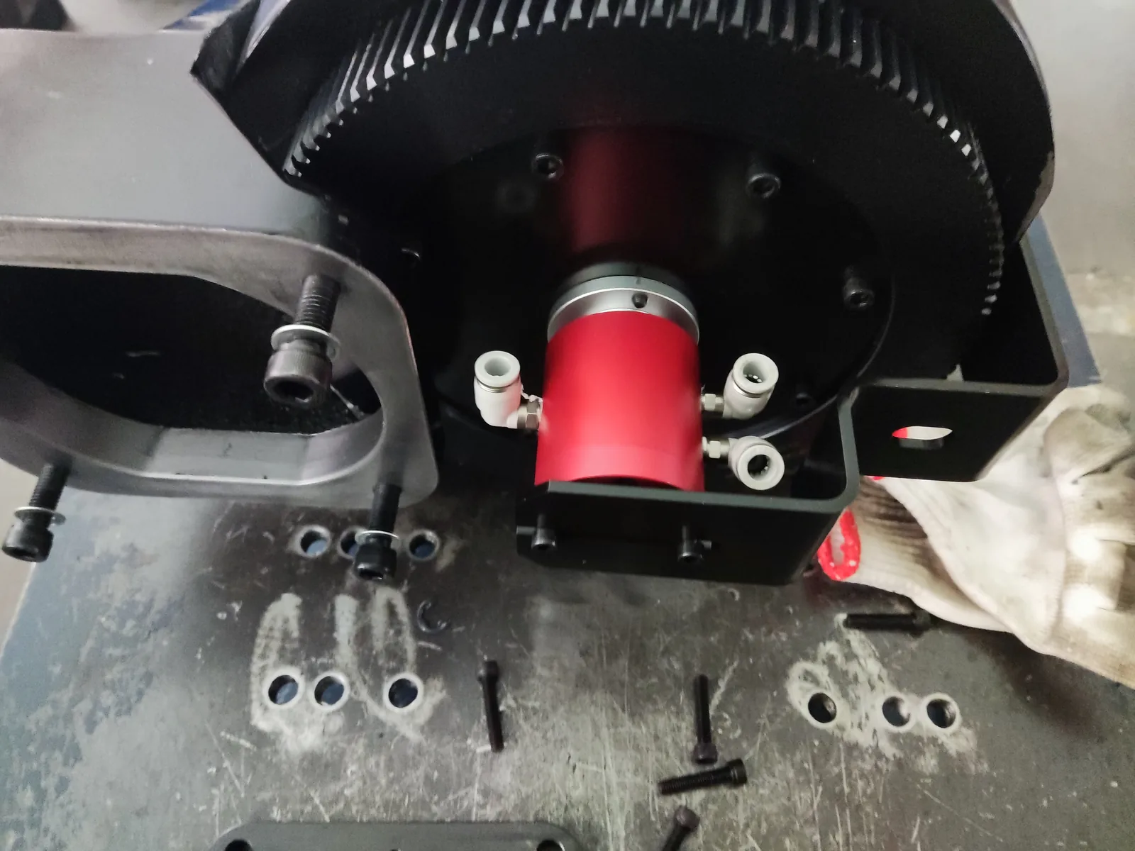 Rear-chuck installationCompressed-air transfer into the rotating rear chuck of a laser tube cutting machine.
A chuck model, photo, or drawing is enough to start
If you already know the air functions, pressure, or speed, include them. We will ask only for the next detail needed to check the fit.
Two or three independent air passages
BP-2P-08-0001 and BP-3P-0004 are used for rear-chuck compressed air. Choose by the number of independently controlled air functions and the required interface.
Three things that narrow the choice
1. Independent air functions
Count the clamp, release, and other air functions that must be controlled separately.
2. Known operating conditions
Share the pressure and maximum or continuous speed if you know them. Incomplete information is fine for the first inquiry.
3. Installation fit
A photo or drawing helps us check the available space, mounting interface, connections, and hose direction.
What helps us recommend a model
Send whatever is already available; you do not need every item for the first inquiry.
| What you may have | What it helps us check |
|---|---|
| Air functions or circuit count | Whether a two- or three-passage layout fits the chuck |
| Pressure and speed | The operating point for the selected model |
| Chuck photo or drawing | Mounting space, interface, connections, and hose direction |
| Existing model or machine reference | The closest catalog model or a custom starting point |
Process and assist gases need a separate solution
These two standard models are for rear-chuck compressed air. For process or assist gas, tell us the gas and operating conditions so materials, cleanliness, and testing can be checked separately.
See a rear-chuck installation
View two workshop photographs showing compressed-air transfer at the rear chuck.
Need a rotary union for a rear chuck?
A chuck model, photo, or drawing is enough to start. If available, include the circuit count, pressure, and speed. We will reply with a suitable standard model or custom option and ask only for any detail that matters next.
Rear-Chuck Pneumatic Rotary Union Questions
Which standard models are used for rear-chuck compressed air?
BP-2P-08-0001 provides two independent passages, and BP-3P-0004 provides three. Choose according to the number of separately controlled air functions and the required interface.
What do I need to send for a model recommendation?
A chuck model, photo, or drawing is enough to start. Add the circuit count, pressure, and speed if they are available.
How are process or assist gases handled?
They require a separate solution. Tell us the gas and operating conditions so we can check materials, cleanliness, and testing.