

Operating Principle
How a Non-Contact Clearance-Seal Rotary Union Works at High Speed
Follow the stationary stator, high-speed rotor, medium flow path, bearing support, and controlled 0.003 mm one-side radial clearance.
Use these practical resources to define operating conditions, compare seal structures, avoid common installation errors, and identify the information needed to select a model.
Begin with the question you need to solve, then move from general guidance to a model or application review.
Review passages, medium, maximum pressure, maximum speed, temperature, and mounting before narrowing the model.
Open the selection guide →Check alignment, hose support, anti-rotation, air preparation, and startup conditions that can affect service life.
Review installation risks →Understand how O-rings, lip seals, and spring-energized PTFE seals differ by pressure, speed, medium, and friction.
Compare seal types →Share the model, medium, operating limits, installation details, and observed symptoms for an engineer-to-engineer review.
Contact an engineer →These four published guides explain the operating principle and the decisions most often needed before model selection, installation, and seal review.
Follow the stationary stator, high-speed rotor, medium flow path, bearing support, and controlled 0.003 mm one-side radial clearance.
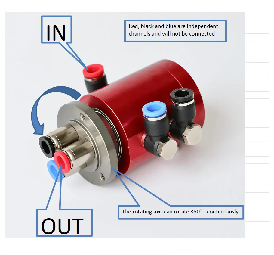
Use passage count, pressure, speed, medium compatibility, and mounting as an initial screen before the drawing and operating conditions are reviewed.
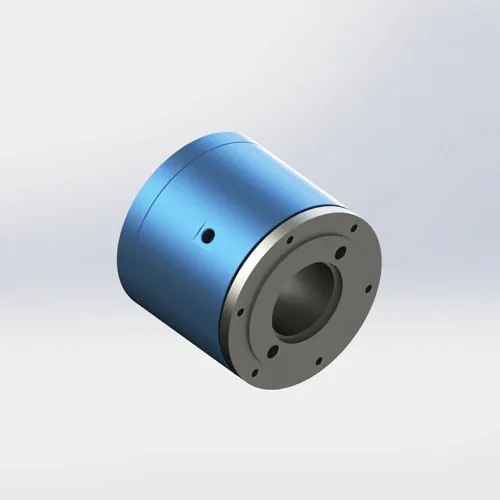
Review mounting, alignment, piping, filtration, lubrication, and commissioning conditions that can contribute to premature wear or leakage.
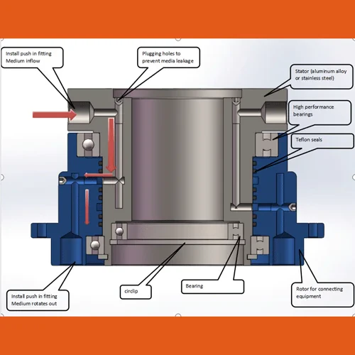
Compare three seal structures by pressure, speed, medium, friction, and acceptable leakage behavior before selecting a configuration.
Use these links to narrow the model, see rotary joints installed in real equipment, or understand how finished units are tested.
Compare passage count, pressure, speed, mounting, material, and typical applications to find the closest starting point.
Compare models →See rotary joints installed in CNC fixtures, bottle-capping machines, and laser tube cutting rear chucks.
View installations →See how every finished pneumatic unit is leak-tested passage by passage with compressed air at 1.0 MPa before packing.
View the testing process →A model number, photo, or drawing is enough to start. If known, add the medium, pressure, speed, passage count, and mounting details.