
Direct answer: In the design illustrated here, the outer stator remains stationary while the central rotor turns at high speed. The medium enters through the side inlet, crosses into a radial passage in the rotor, and then flows upward through the rotor's axial channel. A controlled 0.003 mm one-side radial clearance separates the clearance-seal stator from the rotor, limiting bypass leakage without creating sliding contact at that interface.
This design principle can reduce friction and wear at the rotary sealing interface, but it also makes precision, cleanliness, alignment, bearing support, pressure, temperature, and acceptable leakage important parts of the engineering decision. The illustration explains one design principle; it does not imply that every Begapunk rotary union uses the same internal structure.
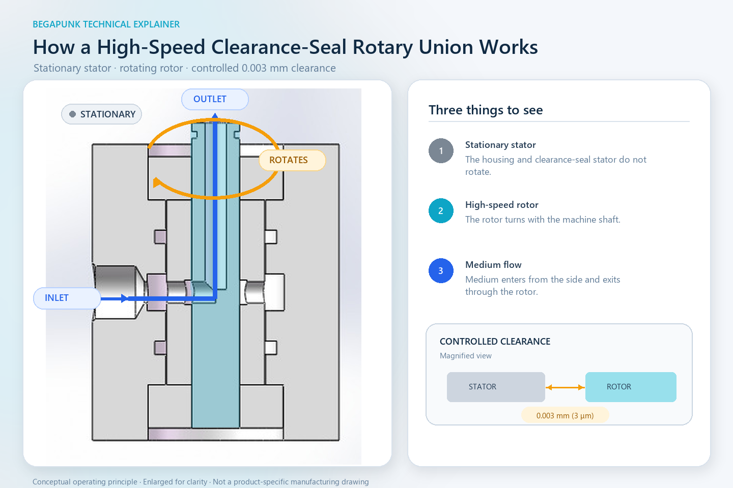
What the Diagram Shows
- Stationary outer stator: the main housing remains fixed relative to the media supply.
- Stationary clearance-seal stator: this precision surface surrounds the rotor but does not rotate with it.
- High-speed rotor: the central blue component rotates with the machine and contains the internal flow passage.
- Bearings: the bearing system supports and locates the rotor so that it can rotate around the intended axis.
- Static sealing rings: these seals control leakage at stationary joints. They are not the dynamic rotor-to-stator sealing interface shown by the 0.003 mm radial gap.
How the Medium Moves from the Stationary Side to the Rotor
Step 1 — Side inlet
The medium enters through the inlet on the stationary side of the housing. The supply pipe does not need to rotate with the machine.
Step 2 — Radial transfer
The medium passes radially from the stationary inlet region into the rotor passage. The precision clearance controls the unwanted flow path between the stationary and rotating surfaces while allowing the rotor to turn without rubbing against the clearance-seal stator.
Step 3 — Axial outlet
The medium turns into the axial channel inside the rotor and exits upward toward the rotating equipment. This provides continuous media transfer without twisting the external supply hose around the rotating shaft.
The drawing shows the operating principle of one passage. A multi-passage rotary union requires independent flow paths and suitable isolation between those paths. Passage count, port assignment, pressure, medium, and mounting arrangement must be confirmed for the actual machine.
Why Use a Non-Contact Clearance Instead of a Rubbing Seal?
A conventional contact seal creates a barrier by pressing a sealing element against a moving surface. That approach can provide strong leakage control, but relative motion also creates friction, heat, and wear. The result depends on seal material, surface finish, lubrication, pressure, temperature, sliding speed, and duty cycle.
A non-contact clearance seal uses a different balance. The stationary and rotating surfaces are separated by a very small engineered gap. Because the surfaces do not rub at this interface, the clearance seal itself does not generate sliding-contact wear in normal operation. This can be valuable when rotational speed makes friction and heat difficult to manage.
Important limitation: “Non-contact” does not mean “zero leakage.” A clearance seal limits flow through a controlled restriction; it does not create a hermetic barrier. Actual leakage depends on the geometry and length of the clearance, pressure difference, medium properties, temperature, rotor position, and the complete internal design.
What Does a 0.003 mm One-Side Radial Clearance Mean?
This is the radial separation on one side between the stationary clearance-seal surface and the rotating rotor in the design shown. It is not the total diametral clearance.
The complete rotating system must preserve the intended separation during assembly and operation. Important factors include rotor and stator concentricity, bearing accuracy and internal clearance, rotor runout and shaft deflection, machining form and surface finish, assembly alignment, thermal expansion, elastic deformation, contamination, vibration, and external piping loads.
If the running gap becomes larger
Bypass leakage can increase, depending on pressure, medium, temperature, and the complete geometry.
If the running gap becomes smaller
The rotor and stator may touch, creating heat, scoring, particles, unstable torque, or damage to the precision surfaces.
The nominal radial clearance is therefore only one part of the design. The tolerance stack and the expected operating condition are equally important.
Why the Bearings Matter to the Seal
The bearings do more than allow rotation. They establish the rotor's position relative to the stationary clearance-seal surface. For a narrow non-contact gap to function, the rotor must remain close to its intended axis.
Bearing selection, fit, internal clearance or preload, lubrication, mounting accuracy, temperature, and external load control can all influence rotor position. A technically precise seal geometry cannot compensate for a rotating assembly that is misaligned or forced sideways by unsupported machine loads.
This is why a rotary union should not be used as the machine's primary radial or axial support unless the approved design specifically assigns that function. External hoses and piping should also be routed and supported so that they do not impose unintended loads on the rotary union.
The Main Trade-Off: Leakage Control Versus Running Clearance
A smaller clearance can restrict bypass flow more effectively, but it also reduces the margin available for runout, thermal growth, deformation, contamination, and assembly variation. A larger clearance provides more mechanical separation but normally allows more bypass flow.
The correct design is not simply “the smallest gap possible.” It is the clearance that remains safe and predictable across the approved pressure, speed, temperature, medium, duty cycle, and manufacturing variation while meeting the project's leakage requirement.
A high-speed clearance-seal design should not be selected by RPM alone. The engineering review must consider the combined operating condition. A maximum pressure value and a maximum speed value listed separately must not be assumed to be available simultaneously.
Where This Design Principle Can Be Useful
A non-contact clearance-seal rotary union may be considered when an application needs continuous media transfer at rotational speeds where sliding friction, seal temperature, or contact wear become important constraints.
Suitability still depends on the actual operating conditions. This architecture may be inappropriate when the application requires near-zero leakage, contains dirty or particle-laden media, experiences large shaft movement, has uncontrolled temperature changes, or cannot maintain the required bearing and alignment accuracy. In those cases, a contact seal, a different non-contact geometry, additional filtration, a controlled drain path, or another rotary-transfer architecture may be more appropriate.
No single sealing principle is best for every machine.
Information Needed Before Selection
- Transfer medium and composition
- Number of independent passages
- Maximum and normal operating pressure
- Maximum and continuous rotational speed
- Medium and ambient temperature
- Expected duty cycle and motion pattern
- Acceptable external and cross-passage leakage
- Required flow rate or allowable pressure drop
- Available installation envelope
- Stationary-side and rotating-side port requirements
- Shaft, mounting, and anti-rotation arrangement
- Available machine drawing or interface model
- Cleanliness, filtration, and maintenance conditions
These inputs help determine whether a clearance-seal design is appropriate and whether the required performance can be maintained across the complete operating range.
Frequently Asked Questions
Does the rotor touch the clearance-seal stator?
Under the intended operating condition, no. Manufacturing variation, runout, thermal growth, contamination, and external loads must be controlled so that the intended 0.003 mm one-side radial clearance is maintained.
Does a non-contact clearance seal provide zero leakage?
No. A clearance seal restricts bypass flow through a narrow engineered gap, but it should not be described as hermetically sealed or zero-leakage without application-specific test evidence.
Why can this principle support high-speed rotation?
There is no sliding contact at the clearance interface during normal operation, so that interface avoids the friction and wear produced by a rubbing dynamic seal. Bearings and other components still have their own speed, lubrication, temperature, and life limits.
Is a 0.003 mm radial clearance suitable for every medium and pressure?
No. Medium viscosity and cleanliness, pressure difference, temperature, required flow, leakage tolerance, bearing behavior, and the complete internal geometry must be reviewed together.
Can this diagram be used as a manufacturing drawing?
No. It is a conceptual cutaway created to explain the operating principle. Product dimensions, tolerances, materials, interfaces, test conditions, and acceptance criteria must be defined in the project-specific drawing and technical agreement.
From Operating Principle to Product Selection
Send the medium, pressure, speed, temperature, passage count, leakage requirement, installation space, and machine drawing when available. Begapunk can review whether a non-contact clearance-seal architecture or another rotary-union design is the safer engineering path for the application.