
BP-3P-S06-0001 Pneumatic and Signal Transfer in a Sensor-Monitored Chuck
This customer configuration transfers three independent compressed-air circuits and external sensor signals across the stationary-to-rotating interface of a pneumatic chuck.
Case Summary
| Item | Application details |
|---|---|
| Product | BP-3P-S06-0001 |
| Application | Sensor-monitored pneumatic chuck |
| Pneumatic functions | Clamping, unclamping and blow-off in this installation |
| Electrical role | Transfer path for external sensor signals across the rotating interface |
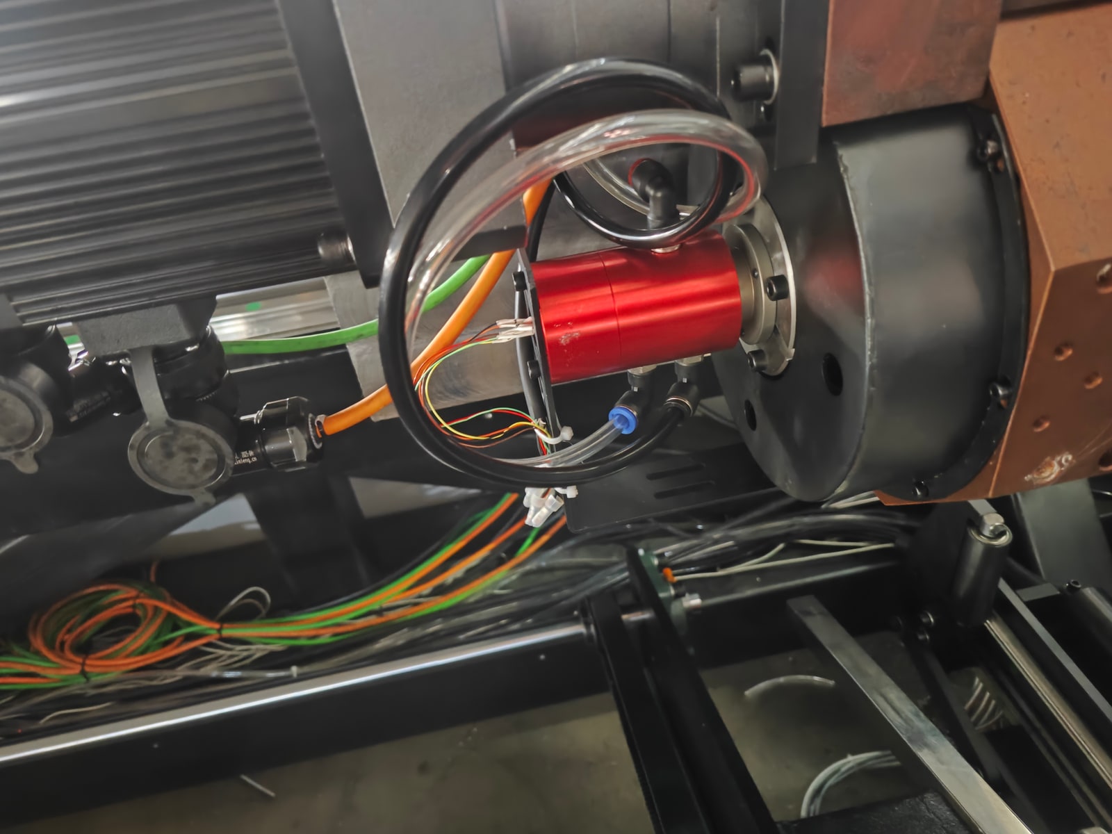
Installed Chuck Integration
The workshop photograph shows the pneumatic rotary union mounted at the chuck assembly, with pneumatic tubing and electrical leads visible around the rotating interface.
What the installation is designed to do
BP-3P-S06-0001 provides separate transfer paths for compressed air and electrical signals. The external sensors and machine controller perform the actual detection; the rotary union does not detect a workpiece or determine clamp status by itself.
Installation Details
- A pneumatic-and-electrical rotary interface is installed at the chuck assembly.
- Pneumatic tubing and electrical leads are routed to the installed unit.
Select the photograph to open the full-resolution JPG.
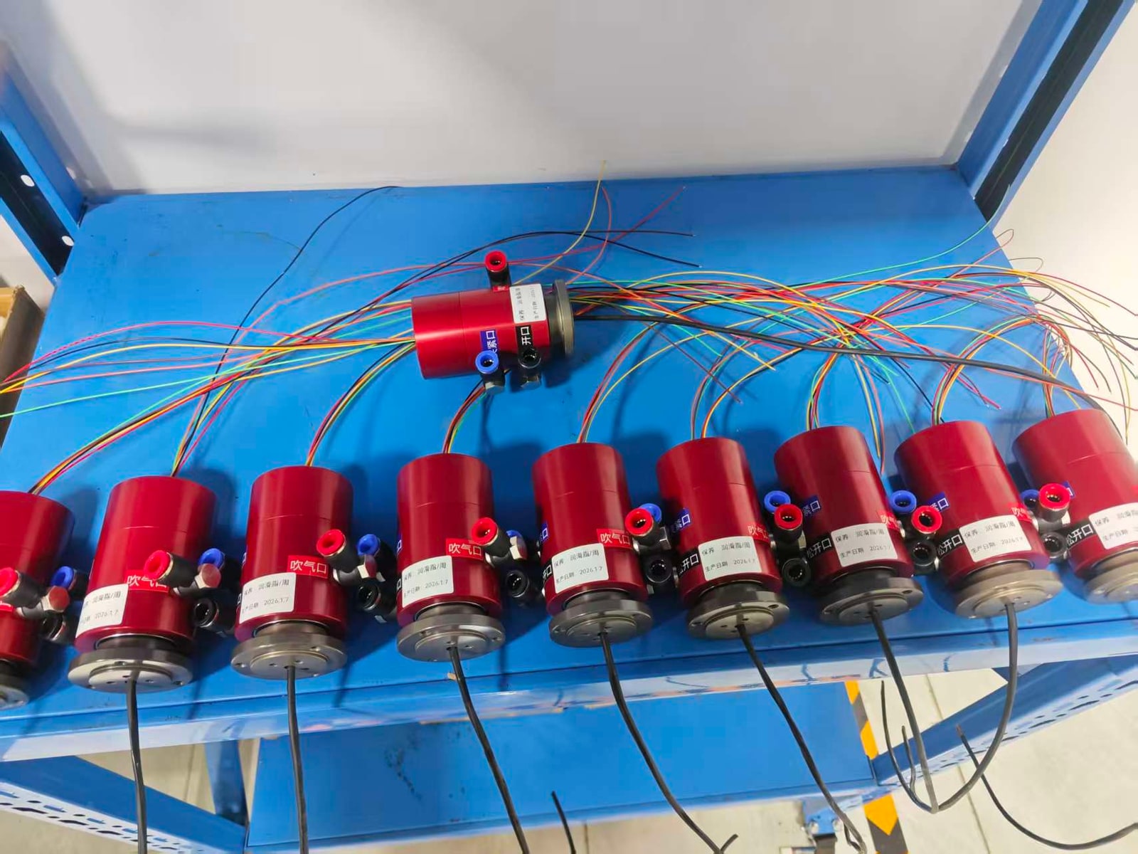
Batch Preparation and Wiring
The second photograph shows multiple units prepared with labeled pneumatic ports and external electrical leads before integration.
Useful production controls
- Keep the customer circuit map matched to each pneumatic port.
- Verify the approved electrical pinout and signal type before wiring.
- Protect tubing and leads from strain, sharp bends and rotating interference.
Circuit Functions in This Installation
These assignments apply to this installation. Port assignments are matched to each chuck circuit diagram.
| Transfer path | Assigned function | System responsibility |
|---|---|---|
| Pneumatic circuit | Clamping | The chuck mechanism performs the clamping action. |
| Pneumatic circuit | Unclamping | The chuck mechanism performs the release action. |
| Pneumatic circuit | Blow-off for dust or chip removal | The machine design determines nozzle location, flow and timing. |
| Electrical signal path | Workpiece-presence or clamped-position confirmation | External sensors and the machine controller perform sensing and logic. |
Integration Checks
For a similar chuck, send the circuit map, operating conditions, chuck drawing and electrical requirements so the configuration can be matched before production.
| Check | Required input | Review objective |
|---|---|---|
| Pneumatic circuit map | Function, medium, pressure and flow for each circuit | Confirm independent paths and correct customer port assignment. |
| Operating conditions | Rotational speed, duty cycle and environment | Confirm suitability for the actual machine conditions. |
| Mechanical interface | Chuck drawing, mounting envelope and hose routing | Check dimensions, concentricity, bend radius and clearance. |
| Electrical interface | Required circuits, voltage, current, signal type, shielding and pinout | Match the slip-ring configuration to the control system. |
| Sensing and safety logic | Sensor type, presence/clamp-state definitions and controller logic | Validate sensing outside the rotary union and complete machine-level safety assessment. |
Review a sensor-monitored chuck integration with Begapunk
Send the chuck drawing, circuit functions, operating conditions and electrical signal requirements for a configuration-specific review.