
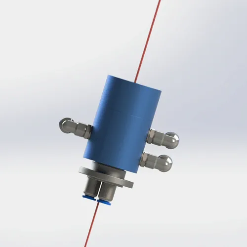
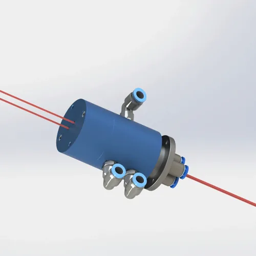
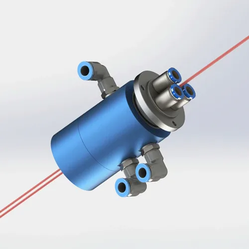
BP-3P-S06-0001 3-Passage Pneumatic-Electrical Rotary Union
- Channels / MOQ
- 3 pneumatic passages · 6 electrical leads · 1 piece; circuit allocation and ratings per selected specification
- Pressure / speed
- 1 MPa (10 bar ≈ 145 psi) · 200 RPM
- Body
- 6061 aluminum alloy
- Seal
- PTFE + O-ring
- Mount
- face A 2×M5, 10 mm deep · face B 3×M5, 8 mm deep
- Production lead time
- About 20 calendar days after payment
Technical Data
Key dimensions and operating limits for this model are listed below.
| Model number | BP-3P-S06-0001 |
|---|---|
| Pneumatic / electrical interface | 3 pneumatic passages · 6 electrical leads · 1 piece; circuit allocation and ratings per selected specification |
| Maximum pressure | 1 MPa (10 bar ≈ 145 psi) |
| Maximum speed | 200 RPM |
| Body material | 6061 aluminum alloy |
| Seal type | PTFE + O-ring |
| Suitable media | Air |
| Temperature range | −20 to +80 °C |
| Weight | 0.41 kg (410 g) |
| Envelope dimensions | Maximum Ø53.95 × 99.8 mm overall |
| Mounting type | face A: 2 × M5, depth 10 mm · face B: 3 × M5, depth 8 mm |
| Port configuration | 3 × Ø4 mm air outlet; the air inlet is assigned in the confirmed drawing before production |
| Warranty period | 1 year from shipment |
Equipment Using Pneumatic Passages and Electrical Leads from BP-3P-S06-0001
BP-3P-S06-0001 combines 3 pneumatic passages with 6 electrical leads. Pneumatic pressure / speed: 1 MPa (10 bar ≈ 145 psi) · 200 RPM; suitable medium: Air. Port arrangement: 3 × Ø4 mm air outlet; the air inlet is assigned in the confirmed drawing before production. Confirm the air inlet, circuit allocation, and electrical ratings for the selected configuration.
Not sure this is the right model?
A model number, photo, drawing, or short description is enough to start. Add any operating details you already know; incomplete information is fine. We’ll check whether BP-3P-S06-0001 fits, or suggest a closer catalog model or custom option.
Ask Us to Check This Model →Installation and Commissioning Guidance
Use the model drawing and the machine installation plan during assembly.
Make the machine safe
Before work, isolate and lock out every energy source, fully depressurize all passages, and prevent any unintended rotation.
Identify the fixed and rotating sides
Orient the rotary union to the machine layout, then align the ports and mounting features before fastening.
Check interfaces before assembly
Match threads, holes, sealing faces, mating dimensions, and orientation exactly. Confirm adapters, tightening torque, and sealant for the selected fittings and mating materials.
Control alignment and external loads
Support hoses and fixed-side hardware so bending, tension, torsion, misalignment, and machine loads are not transferred into the rotary joint.
Use the listed medium
Contact us before using another medium so seal and wetted-material compatibility can be checked.
Commission under controlled conditions
Start at low pressure and speed within the listed limits. Check every passage for leakage and monitor friction, temperature, vibration, and abnormal noise before increasing duty.
Downloads and Engineering Files
2D engineering drawing (PDF)
Model drawing with dimensions, ports, mounting features, and published technical values.
Download 3D Model (.step)
3D STEP model (AP214) for the selected configuration and fit check.
General installation manual (PDF)
General handling, alignment, connection, commissioning, and maintenance guidance.
Inspection Documents
Need an inspection record or material document? Include the requirement with your inquiry.
Three Common Installation and Startup Errors
Avoid these mistakes to reduce leakage, abnormal wear, and commissioning rework.
Transferring piping loads into the rotary union
Hose tension, bending, twisting, rigid restraint, or misalignment can add side load to the rotary union. Support the piping and leave enough natural movement to avoid loading the union.
Connecting ports before checking the interface
Confirm each port function, thread, and sealing method before installation. Do not copy another model’s interface or use media ports as mounting holes.
Starting at full operating conditions
Begin commissioning at low pressure and speed, then increase gradually to the actual operating condition while checking every passage for leakage, temperature rise, vibration, and abnormal noise.
Related Products
Compare nearby models using each model’s published specifications.
BP-3P-S06-0001 FAQs
Is BP-3P-S06-0001 suitable for my machine?
BP-3P-S06-0001 combines 3 pneumatic passages with 6 electrical leads. Suitable medium: Air. Confirm the air inlet, circuit allocation, and electrical ratings for the selected configuration. Mounting: face A: 2 × M5, depth 10 mm · face B: 3 × M5, depth 8 mm.
What are the maximum pressure and speed for BP-3P-S06-0001?
Maximum pressure: 1 MPa (10 bar ≈ 145 psi). Maximum speed: 200 RPM. For continuous rotation, send your duty cycle. We will confirm the operating point before production.
Can BP-3P-S06-0001 be used with vacuum, water, or hydraulic oil?
BP-3P-S06-0001’s catalog rating covers compressed air only. Vacuum, water, and hydraulic oil require a medium-specific engineering review and written compatibility confirmation. Send the medium, pressure, temperature, and speed so we can confirm the required seals, materials, and configuration.
What pneumatic and electrical interfaces does BP-3P-S06-0001 provide?
Pneumatic outlets: 3 × Ø4 mm air outlet; the air inlet is assigned in the confirmed drawing before production. Electrical: 6 leads. Confirm the air inlet, circuit allocation, and electrical ratings for the selected configuration. Mounting: face A: 2 × M5, depth 10 mm · face B: 3 × M5, depth 8 mm.
How do I get a quote for BP-3P-S06-0001?
The model number is enough to start. A photo, drawing, or any operating details you already know can help us confirm the fit. The 3D STEP model for this model is available in the Downloads panel; send the operating conditions for a quotation. We normally reply within one business day.
Continue Reading
Need a Different Configuration?
Send what you already have. We’ll reply with a catalog model or custom option, quotation, estimated lead time, and the relevant 2D drawing and 3D STEP model.
Ask About Another Option →A model number, photo, drawing, or short description is enough to start. We do not use your inquiries or drawings for marketing or public display.