
BP-2P-95-0005 Pneumatic Chuck Integration Case
BP-2P-95-0005 supplies compressed air from the stationary side to the rotating chuck in this customer installation. The photographs show the mounting position and pneumatic hose routing.
Case Summary
| Item | Application details |
|---|---|
| Product | BP-2P-95-0005 |
| Application | Pneumatic chuck assembly |
| Medium | Compressed air |
| Integration type | Stationary-to-rotating compressed-air connection at the chuck |
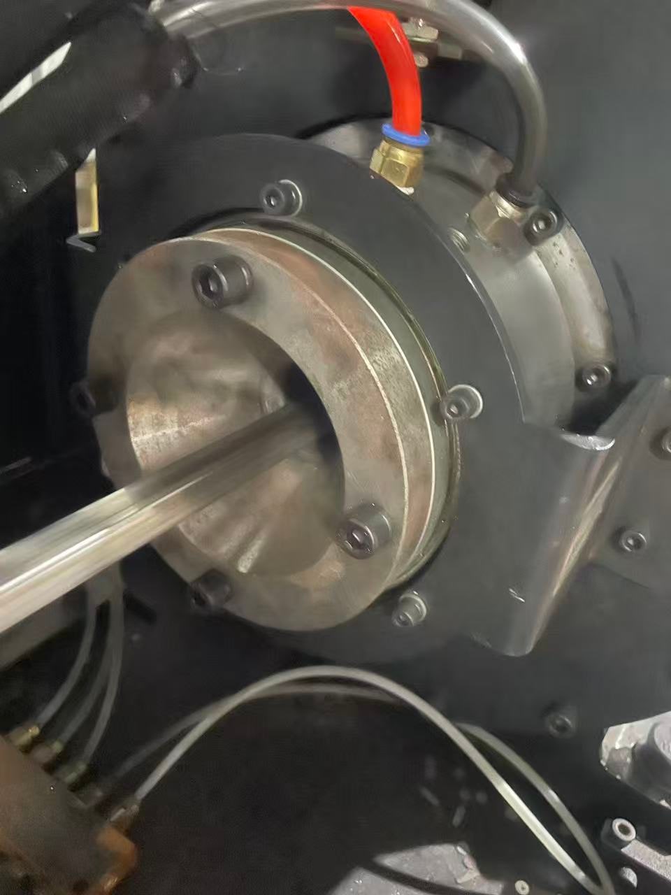
Connection Detail
The close view shows the rotary-union mounting area and two pneumatic hoses routed inside the chuck assembly.
Engineering purpose
The arrangement provides a compact connection between stationary air lines and rotating chuck components.
Before design release
- Confirm the required pneumatic circuits and the ordered product configuration.
- Check port orientation, hose bend radius and interference clearance.
- Verify mounting dimensions against the approved drawing for the ordered unit.
Select the photograph to open the full-resolution JPG.
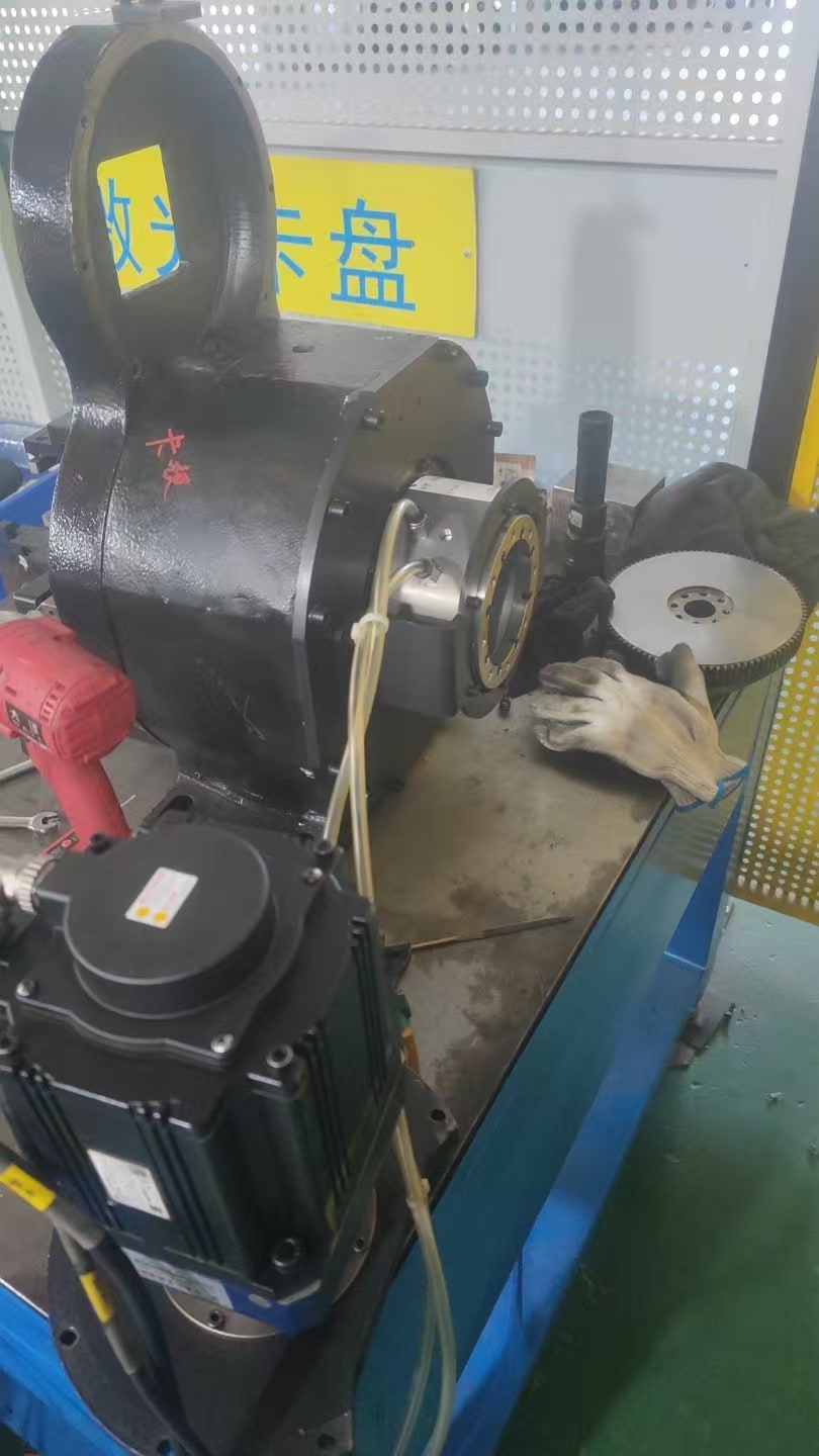
Assembly Overview
The overview photograph records the relationship between the chuck, drive section, fixed-side pneumatic lines and the rotary-union installation area during workshop assembly.
Installation Details
- The rotary union is located close to the chuck's axis.
- The stationary-side hoses approach the union without rotating with the chuck.
- The installation occupies a confined central area within the photographed assembly.
For a Similar Installation
Send the pressure, rotational speed, duty cycle, available clearances, chuck drawing and required interface before machining the mating parts.
Engineering Checks for a Similar Installation
Use the application data below for engineering review before ordering or machining mating components.
| Check | Customer input | Review objective |
|---|---|---|
| Pneumatic demand | Circuit functions and working medium | Match the required flow paths to the ordered configuration. |
| Operating conditions | Pressure, speed and duty cycle | Confirm suitability in writing for the actual machine conditions. |
| Mechanical interface | Chuck drawing, available envelope and mounting arrangement | Check dimensions, concentricity and interference clearance. |
| Hose routing | Port direction, hose size and bend radius | Keep external hose loads away from the rotating interface. |
Review a pneumatic chuck integration with Begapunk
Send the chuck drawing, pneumatic requirements, mounting envelope and operating conditions for a model-specific engineering review.